

WYMIANA USZCZELKI GŁOWICY
 |
| 1. | Clean all surfaces of cylinder block and cylinder heads. |
| 2. | Clean cylinder block front and rear gasket surfaces using a suitable solvent. |
| CAUTION: | The head gaskets (1) are interchangeable between left and right sides. They are marked “UP” to indicate direction to face up. |
 |
| NOTE: | Rotate crankshaft 45°, so that all pistons are ½ the way down the cylinder bore to avoid piston to valve contact. |
| 3. | Position new cylinder head gaskets (5) onto the cylinder block. |
| 4. | Position cylinder heads (4) in place. |
 |
| 5. | Install head bolts. |
| 6. | Tighten the cylinder head bolts in four steps using the sequence shown: |
- Step 1 - Tighten bolts 1-10 to 34 N·m (25 ft. lbs.) and bolts 11-15 to 20 N·m (15 ft. lbs.) in the sequence shown.
- Step 2 - Tighten bolts 1-1 0 to 54 N·m (40 ft. lbs.) and verify bolts 11-15 are 20 N·m (15 ft. lbs.) in the sequence shown.
- Step 3 - Rotate bolts 1-10 an additional 90 degrees in the sequence shown.
- Step 4 - Tighten bolts 11-15 to 34 N·m (25 ft. lbs.) in the sequence shown.
 |
| CAUTION: | Pushrods and rocker arm assemblies must be installed in their original locations or engine damage could result. |
| 7. | Install Pushrod retainer (1) on cylinder head. |
| 8. | Install intake pushrods in their original position and snap push rods into Pushrod Retainer (1). |
| 9. | Install intake rocker shaft and remove Pushrod Retainer (1). |
| 10. | Install exhaust pushrods and rocker shaft. |
| 11. | Install the intake manifold and throttle body assembly |
| 12. | Install the spark plugs. |
| 13. | Connect the heater hoses. |
| 14. | Install the fuel supply line. |
| 15. | Install the power steering pump. |
| 16. | Install the accessory drive belt |
|
| 17. | Install cylinder head covers (1) |
 |
| 18. | Install the ignition coils (1) |
 |
| 19. | Connect the ignition coil electrical connectors (1) and injector electrical connectors. |
 |
| 20. | Connect the evaporation control system. |
| 21. | Install the air cleaner housing and connect to throttle body. |
| 22. | Connect make-up air hose (1), and vacuum lines. |
| 23. | Connect intake air temperature sensor (4) electrical connector. |
 |
| 24. | Fill cooling system |
| 25. | Connect the negative cable to the battery (1). |
 |
| 26. | Install engine covers (1). |
| 27. | Start engine check for leaks. |
TABELA WARTOŚCI MOMENTÓW DOKRĘCANIA
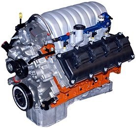
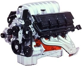
6.1L ENGINE
SPECIFICATIONS
GENERAL DESCRIPTION
DESCRIPTION |
SPECIFICATION |
|---|---|
| Engine Type | 90° V-8 OHV |
| Displacement | 6.1 Liters |
| 370 (Cubic Inches) | |
| Bore | 103 mm (4.055 in.) |
| Stroke | 90.9 mm (3.58 in.) |
| Compression Ratio | 10.3:1 |
| Firing Order | 1-8-4-3-6-5-7-2 |
| Lubrication | Pressure Feed - Full Flow Filtration |
| Cooling System | Liquid Cooled - Forced Circulation |
| Cylinder Block | Cast Iron |
| Cylinder Head | Aluminum |
| Crankshaft | Forged Steel |
| Camshaft | Cast Iron |
| Pistons | Aluminum Alloy |
| Connecting Rods | Powdered Metal |
CYLINDER BLOCK
DESCRIPTION |
SPECIFICATION |
|
|---|---|---|
Metric |
Standard |
|
| Cylinder Bore Diameter | 103 mm | 4.055 in. |
| Out of Round (MAX) | 0.008 mm | 0.0003 in. |
| Taper (MAX) | 0.0127 mm | 0.0005 in. |
| Lifter Bore Diameter | 21.45 - 21.425 mm | 0.8444 - 0.8435 in. |
PISTONS
DESCRIPTION |
SPECIFICATION |
|
|---|---|---|
Metric |
Standard |
|
| Clearance Measured at 38.0 mm (1.5 in.) Below Deck | 0.0245 - 0.0515 mm | 0.00096 - 0.0020 in. |
| Ring Groove Diameter | ||
| Groove #1 | 93.1 - 93.4 mm | 3.665 - 3.677 in. |
| Groove #2 | 91.6 - 91.8 mm | 3.606 - 3.614 in. |
| Weight | 435 grams | 15.34 oz. |
| Piston Length | 54.70 - 55.30 mm | 2.153 - 2.177 in. |
| Ring Groove Width | ||
| No. 1 | 1.51 - 1.54 mm | 0.0594 - 0.0606 in |
| No. 2 | 1.51 - 1.53 mm | 0.0594 - 0.0602 in. |
| No. 3 | 3.030 - 3.055 mm | 0.1192 - 0.1202 in. |
PISTON PINS
DESCRIPTION |
SPECIFICATION |
|
|---|---|---|
Metric |
Standard |
|
| Clearance In Piston | 0.006 - 0.015 mm | 0.00023 - 0.00059 in. |
| Diameter | 25.0 - 25.003 mm | 0.9843 - 0.9844 in. |
| Length | 64.785 - 65.215 mm | 2.551 - 2.568 in. |
PISTON RINGS
DESCRIPTION |
SPECIFICATION |
|
|---|---|---|
Metric |
Standard |
|
| Ring Gap | ||
| Top Compression Ring | 0.30 - 0.40 mm | 0.0118 - 0.0157 in. |
| Second Compression Ring | 0.35 - 0.60 mm | 0.0137 - 0.0236 in. |
| Oil Control (Steel Rails) | 0.20 - 0.71 mm | 0.0079 - 0.028 in. |
| Side Clearance | ||
| Top Compression Ring | 0.02 - 0.068 mm | 0.0007 - 0.0026 in. |
| Second Compression Ring | 0.02 - 0.058 mm | 0.0007 - 0.0022 in. |
| Oil Ring (Steel Ring) | 0.019 - 0.229 mm | 0.0007 - 0.0091 in. |
| Ring Width | ||
| Top Compression Ring | 1.472 - 1.490 mm | 0.0579 - 0.0586 in. |
| Second Compression Ring | 1.472 - 1.490 mm | 0.0579 - 0.0586 in. |
| Oil Ring (Steel Rails) | 0.447 - 0.473 mm | 0.0175 - 0.0186 in. |
CONNECTING RODS
DESCRIPTION |
SPECIFICATION |
|
|---|---|---|
Metric |
Standard |
|
| Piston Pin Bore Diameter | 23.955 - 23.975 mm | 0.9431 - 0.9438 in. |
| Side Clearance | 0.10 - 0.35 mm | 0.003 - 0.0137 in. |
CRANKSHAFT
DESCRIPTION |
SPECIFICATION |
|
|---|---|---|
Metric |
Standard |
|
| Main Bearing Journal Diameter | 64.988 - 65.012 mm | 2.5585 - 2.5595 in. |
| Bearing Clearance | 0.023 - 0.051 mm | 0.0009 - 0.002 in. |
| Out of Round (MAX) | 0.005 mm | 0.0002 in. |
| Taper (MAX) | 0.003 mm | 0.0001 in. |
| End Play | 0.052 - 0.282 mm | 0.002 - 0.011 in. |
| End Play (MAX) | 0.282 mm | 0.011 in. |
| Connecting Rod Journal Diameter | 53.992 - 54.008 mm | 2.125 - 2.126 in. |
| Bearing Clearance | 0.020 - 0.074 mm | 0.0007 - 0.0029 in. |
| Out of Round (MAX) | 0.005 mm | 0.0002 in. |
| Taper (MAX) | 0.003 mm | 0.0001 in. |
CAMSHAFT
DESCRIPTION |
SPECIFICATION |
|
|---|---|---|
Metric |
Standard |
|
| Bearing Journal Diameter | ||
| No. 1 | 58.2 mm | 2.29 in. |
| No. 2 | 57.8 mm | 2.27 in. |
| No. 3 | 57.4 mm | 2.26 in. |
| No. 4 | 57.0 mm | 2.24 in. |
| No. 5 | 43.633 mm | 1.72 in. |
| Bearing To Journal Clearance Standard | ||
| No. 1 | 0.040 - 0.080 mm | 0.0015 - 0.003 in. |
| No. 2 | 0.050 -0.090 mm | 0.0019 - 0.0035 in. |
| No. 3 | 0.040 - 0.080 mm | 0.0015 - 0.003 in. |
| No. 4 | 0.050 - 0.090 mm | 0.0019 - 0.0035 in. |
| No. 5 | 0.040 - 0.080 mm | 0.0015 - 0.003 in. |
| Camshaft End Play | .080 - 0.290 mm | 0.0031 - 0.0114 in. |
VALVE TIMING
DESCRIPTION |
SPECIFICATION |
|---|---|
| Intake | |
| Opens (BTDC) | 15.0° |
| Closes (ATDC) | 268.0° |
| Duration | 283.0° |
| Exhaust | |
| Opens (BTDC) | 251° |
| Closes (ATDC) | 35° |
| Duration | 286.0° |
| Valve Overlap | 50° |
CYLINDER HEAD
DESCRIPTION |
SPECIFICATION |
|
|---|---|---|
Metric |
Standard |
|
| Valve Seat Angle | 44.5° - 45.0° | |
| Valve Seat Runout (MAX) | 0.05 mm | 0.0019 in. |
| Valve Seat Width | ||
| Intake | 1.18 - 1.62 mm | 0.0464 - 0.0637 in. |
| Exhaust | 1.48 - 1.92 mm | 0.0582 - 0.0755 in. |
| Guide Bore Diameter | 7.975 - 8.00 mm | 0.313 - 0.314 in. |
HYDRAULIC TAPPETS
DESCRIPTION |
SPECIFICATION |
|
|---|---|---|
Metric |
Standard |
|
| Body Diameter | 21.387 - 21.405 mm | 0.8420 - 0.8427 in. |
| Clearance (To Bore) | 0.020 - 0.063 mm | 0.0007 - 0.0024 in. |
| Dry Lash (at the valve) | 3.0 mm | 0.1181 in. |
VALVES
DESCRIPTION |
SPECIFICATION |
|
|---|---|---|
Metric |
Standard |
|
| Face Angle | ||
| Intake | 45.5° - 46.0° | |
| Exhaust | 45.0° - 45.5° | |
| Head Diameter | ||
| Intake | 52.67 - 52.93 mm | 2.07 - 2.08 in. |
| Exhaust | 40.37 - 40.63 mm | 1.57 - 1.60 in. |
| Length (Overall From Gage Line) | ||
| Intake | 124.38 - 124.76 mm | 4.897 - 4.912 in. |
| Exhaust | 122.47 - 122.85 mm | 4.822 - 4.837 in. |
| Stem Diameter | ||
| Intake | 7.734 - 7.954 mm | 0.312 - 0.313 in. |
| Exhaust | 7.930 - 7.950 mm | 0.312 - 0.313 in. |
| Stem - to - Guide Clearance | ||
| Intake | 0.021 - 0.066 mm | 0.0008 - 0.0025 in. |
| Exhaust | 0.025 - 0.070 mm | 0.0010 - 0.0028 in. |
| Valve Lift ( @ Zero Lash) | ||
| Intake | 14.5 mm | 0.571 in. |
| Exhaust | 14.0 mm | 0.551 in. |
VALVE SPRING
DESCRIPTION |
SPECIFICATION |
|
|---|---|---|
Metric |
Standard |
|
| Spring Force (Valve Closed) | ||
| Intake | 445.0 N +/- 22.0 N @ 47.5 mm | 99.0 lbs +/- 4.0 - 9.0 lbs. @ 1.870 in. |
| Exhaust | 445.0 N +/- 22.0 N @ 45 mm | 99.0 lbs +/- 4.0 - 9.0 lbs. @ 1.772 in. |
| Spring Force (Valve Open) | ||
| Intake | 1450.0 N +/- 68.0 N @ 33.0 mm | 325.5 lbs. +/- 15.3 lbs. @ 1.3 in. |
| Exhaust | 1450.0 N +/- 68.0 N @ 31.0 mm | 325.5 lbs. +/- 15.3 lbs. @ 1.22 in. |
| Free Length (approx) | ||
| Intake | 54.2 mm | 2.133 in. |
| Exhaust | 51.4 mm | 2.023 in. |
| Number of Coils | ||
| Intake | 7.35 | |
| Exhaust | 7.0 | |
| Wire Diameter | ||
| Intake and Exhaust | 5.65 × 4.51 mm | 0.222 - 0.178 in. |
| Installed Height (Spring Seat to Bottom of Retainer) | ||
| Intake | 47.5 mm | 1.870 in. |
| Exhaust | 45.0 mm | 1.772 in. |
OIL PUMP
DESCRIPTION |
SPECIFICATION |
|
|---|---|---|
Metric |
Standard |
|
| Clearance Over Rotors (MAX) | 0.095 mm | 0.0038 in. |
| Outer Rotor to Pump Body Clearance (MAX) | 0.235 mm | 0.009 in. |
| Tip Clearance Between Rotors (MAX) | 0.150 mm | 0.006 in. |
OIL PRESSURE
SPECIFICATION |
SPECIFICATION |
|---|---|
| At Curb Idle Speed (MIN)* | 25 kPa (4 psi) |
| @ 3000 rpm | 170 - 758 kPa (25 - 110 psi) |
| * CAUTION: If pressure is zero at curb idle, DO NOT run engine | |