
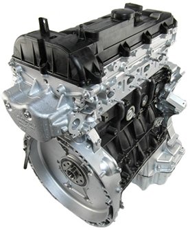
WYMIANA USZCZELKI GŁOWICY
| WARNING: |
|
NO FIRE, OPEN FLAMES OR SMOKING. SERVICE VEHICLES IN WELL VENTILATED AREAS. RISK OF POISONING FROM INHALING OR SWALLOWING FUEL. RISK OF INJURY FROM SKIN AND EYE CONTACT WITH FUEL. WEAR PROTECTIVE CLOTHING. |
| NOTE: |
Thoroughly clean all mating surfaces with appropriate solvents and blow out bolt holes, to assure that no grease or oil is present during reassembly. |
| NOTE: |
If piston or connecting rods have been replaced, measure piston projection. |
| NOTE: |
Check facing on cylinder head contact surface. |
 |
- Install cylinder head assembly on engine block.
NOTE: The M12 cylinder head bolts must be tightened in 5 stages.
NOTE: M12 bolts are (1 - 10) and M8 bolts are (11 - 13).
- Install M12 cylinder head bolts. Tighten bolts in numeric order starting with number 1 to 10 N·m (89 in. lbs.).
- Install M8 cylinder head-to-timing chain cover bolts. Tighten bolts (11, 12, and 13) to 20 N·m (177 in. lbs.).
- Tighten M12 cylinder head bolts in numeric order starting with number 1 to:
- 50 N·m (37 ft. lbs.).
- Plus an additional 90 °
- Plus an additional 90 °
- Plus an additional 90 °
- Plus an additional 90 °
- Install the hydraulic lifters into cylinder head.
- Install the rocker arms into cylinder head.


- Install the camshafts


- Connect the glow plug (2) harness connectors.


- Install the coolant recovery reservoir (1). Tighten bolts (3) to 4 N·m (35 in. lbs.).
- Connect the coolant hoses (2 and 4).
- Install the intake manifold


- Install the exhaust manifold


- Fill the cooling system
- Install the belly pan.
- Install the air inlet tube to the turbocharger.
- Install the air cleaner housing assembly
- Connect the negative battery cable.
- Start engine and check for leaks.


- Install engine cover (1).
- Install the air inlet duct (2) and lock the quarter turn lock tabs (1).
TABELA WARTOŚCI MOMENTÓW DOKRĘCANIA
| DESCRIPTION | N·m | Ft. Lbs. | In. Lbs. |
|---|---|---|---|
|
A/C Compressor Bolts |
32 |
24 |
— |
|
A/C Compressor Bracket Bolts |
45 |
33 |
— |
|
A/C Compressor Lines at Compressor |
20 |
— |
177 |
|
Accessory Drive Belt Tensioner |
|||
|
M8 Bolt |
20 |
— |
177 |
|
M10 Bolt |
45 |
33 |
— |
|
Accessory Drive Idler Pulley Bolt |
45 |
33 |
— |
|
Accessory Carrier |
|||
|
M6 |
9 |
— |
80 |
|
M8 |
20 |
— |
177 |
|
Air Cleaner Bracket Bolt |
9 |
— |
80 |
|
Air Cleaner Mounting Bracket Bolt |
11 |
— |
97 |
|
Air Cleaner Mounting Bracket Nut |
11 |
— |
97 |
|
Air Temp/Pressure Sensor |
8 |
— |
70 |
|
Balance Shaft/Crankshaft Bearing Cap Bolts |
60 + 90° |
44 + 90° |
— |
|
Balance Shaft Drive Gear Bolts |
50 + 90° |
37 + 90° |
— |
|
Battery Clamp Bolt |
7 |
— |
62 |
|
Battery Tray Bolts |
11 |
— |
97 |
|
Battery Tray Nut |
11 |
— |
97 |
|
Boost Pressure Sensor Bolts |
8 |
— |
71 |
|
Camshaft Bearing Cap Bolts |
INSTALLATION |
||
|
Camshaft Position (CMP) Sensor |
9 |
— |
80 |
|
Camshaft Sprocket Bolt |
55 + 90° |
41 + 90° |
— |
|
Charge Air Cooler (CAC) Clamp — Intercooler Side |
25 |
18 |
— |
|
Charge Air Cooler (CAC ) Clamp — Turbocharger Side |
5 |
— |
44 |
|
Charge Air Muffler Bracket Bolt |
9 |
— |
80 |
|
Charge Air Cooler Tube Bolt |
9 |
— |
80 |
|
Coolant Recovery Bottle |
4 |
— |
35 |
|
Connecting Rod Caps Bolts |
|||
|
Crankshaft Position (CKP) Sensor |
8 |
— |
71 |
|
Cylinder Head Bolts |
|||
|
Cylinder Head Cover Bolts |
9 |
— |
80 |
|
Cylinder Head to Timing Chain Cover Bolts |
20 |
— |
177 |
|
DRV Valve |
|||
|
EGR Air Flow Control Valve |
9 |
— |
80 |
|
EGR Back Pressure Transducer |
25 |
18 |
— |
|
EGR Bypass Vacuum Diaphragm Bolts |
12 |
— |
106 |
|
EGR Bypass Valve Bolts |
9 |
— |
80 |
|
EGR Cooler Bolts |
9 |
— |
80 |
|
EGR Cooler Support Bracket Bolts |
9 |
— |
80 |
|
EGR Crossover Pipe to Exhaust Manifold Bolts |
12 + 90° |
— |
106 + 90° |
|
EGR Crossover Pipe Heat Shield Bolts |
8 |
— |
71 |
|
EGR Crossover Pipe to Upper Chain Case Cover Bolts |
9 |
— |
80 |
|
EGR Cooler Manifold Bolts |
9 |
— |
80 |
|
EGR Support Bracket Bolts |
9 |
— |
80 |
|
EGR Temperature Sensor |
45 |
33 |
— |
|
EGR Tube Bolts |
9 |
— |
80 |
|
EGR Vacuum Solenoid Bolts |
9 |
— |
80 |
|
EGR Valve Bolts |
15 |
— |
133 |
|
Engine Lifting Bracket Front |
9 |
— |
80 |
|
Engine Lifting Bracket Rear |
9 |
— |
80 |
|
Engine Carrier Mount at Engine Block Bolts |
25 |
18 |
— |
|
Engine Mount Bracket Bolt |
68 |
50 |
— |
|
Engine Mount to Frame Rail Bolts |
75 |
55 |
— |
|
Engine Mount Through Bolt |
88 |
65 |
— |
|
Exhaust Flex Coupler to Catalytic Converter Nuts |
29 |
21 |
— |
|
Exhaust Manifold Nuts |
30 |
22 |
— |
|
Exhaust Manifold Heat Shield Bolts |
8 |
— |
71 |
|
Flywheel Bolts |
45 + 100° |
33 + 100° |
— |
|
Front Coolant Tube Bolts |
9 |
— |
80 |
|
Front Fore/aft Member Bolts |
78 |
58 |
— |
|
Front Roll Mount Through Bolt |
65 |
48 |
— |
|
Front Roll Mount to Fore/aft Member |
63 |
46 |
— |
|
Front Oil Seal Carrier |
9 |
— |
80 |
|
Fuel Injector Tensioning Claw Bolt |
15 + 90° |
— |
133 + 90° |
|
Stage 2 |
+ 90° |
— |
+ 90° |
|
Fuel Injector Pressure Lines at Injector Union Nut |
|||
|
Stage 1 |
7 |
— |
62 |
|
Stage 2 |
33 |
24 |
— |
|
Fuel Injector Pressure Lines at Fuel Rail Union Nut |
|||
|
Stage 1 |
7 |
— |
62 |
|
Stage 2 |
33 |
24 |
— |
|
Fuel Line Bracket Bolts |
9 |
— |
80 |
|
Fuel Line Heat Shield Bolts |
9 |
— |
80 |
|
Fuel Rail Bolts |
14 |
— |
124 |
|
Fuel Return Line Banjo Bolt |
32 |
24 |
— |
|
Generator Bolts |
20 |
— |
177 |
|
Generator B+ Nut |
18 |
— |
159 |
|
Generator Bracket |
54 |
40 |
— |
|
Generator D+ Nut |
4 |
— |
35 |
|
Glow Plugs |
11 |
— |
97 |
|
Glow Plugs Module Bolts |
9 |
— |
80 |
|
Glow Plugs Module Ground Wire Bolts |
9 |
— |
80 |
|
High Pressure Fuel Feed Line at High Pressure Pump Union Nut |
|||
|
Stage 1 |
7 |
— |
62 |
|
Stage 2 |
33 |
24 |
— |
|
High Pressure Fuel Feed Line at Fuel Rail Union Nut |
|||
|
Stage 1 |
7 |
— |
62 |
|
Stage 2 |
33 |
24 |
— |
|
High Pressure Fuel Line P-clamp Bolts |
9 |
— |
80 |
|
Idler Pulley Bolt |
45 |
33 |
— |
|
Intake Manifold Bolts |
14 |
— |
124 |
|
Intermediate Gear to Engine Block Bolt |
80 |
59 |
— |
|
Knock Sensor |
20 |
— |
177 |
|
Main Bearing Caps Bolts |
|||
|
Mixing Chamber Bolts |
9 |
— |
80 |
|
Mixing Chamber Support Bracket Bolts |
9 |
— |
80 |
|
Oil Control Valve |
20 |
— |
177 |
|
Oil Cooler Bolts |
10 |
— |
89 |
|
Oil Cooler Adapter to Engine Block Bolts |
20 |
— |
177 |
|
Oil Dipstick Tube Bolt |
9 |
— |
80 |
|
Oil Drain Plug |
27 |
20 |
— |
|
Oil Filter Cap |
25 |
18 |
— |
|
Oil Filter Housing Bolts |
|||
|
M6 Bolt |
10 |
— |
89 |
|
M8 Bolt |
20 |
— |
177 |
|
Oil Jet |
5 |
— |
44 |
|
Oil Level Sensor |
9 |
— |
80 |
|
Oil Pan Bolts |
|||
|
Oil Pump Bolts |
6 + 90° |
— |
53 + 90° |
|
Oil Pump Suction Tube Bolts |
6 + 90° |
— |
53 + 90° |
|
Oil Temperature Sensor |
18 |
13 |
— |
|
Power Steering Pressure Hose at Steering Gear |
32 |
24 |
— |
|
Power Steering Pressure Hose at Pump |
32 |
24 |
— |
|
Power Steering Pressure Hose Support Bracket Bolt |
9 |
— |
80 |
|
Power Steering Pump/Water Pump to Oil Pan Bolts |
20 |
— |
177 |
|
Power Steering Pump Bracket at Pump |
14 |
— |
124 |
|
Power Steering Pump Bracket at Engine Block Bolts |
9 |
— |
80 |
|
Rear Fore/aft Member Bolt |
129 |
95 |
— |
|
Rear Roll Mount to Crossmember Bolts |
153 |
112 |
— |
|
Rear Roll Mount Through Bolt |
65 |
48 |
— |
|
Starter Motor Bolts |
40 |
30 |
— |
|
Starter Motor B+ Cable Nut |
14 |
— |
124 |
|
Starter Motor Relay Cable Nut |
6 |
— |
53 |
|
Swirl Valve Actuator Bolts |
9 |
— |
80 |
|
Thermostat Housing to Engine Block Bolts |
9 |
— |
80 |
|
Timing Chain Press Thrust Spindle |
32 |
24 |
— |
|
Timing Chain Tensioner |
70 |
52 |
— |
|
Timing Cover to Engine Block Bolts |
20 |
— |
177 |
|
Transmission to Engine Bolts |
48 |
35 |
— |
|
Transmission Mount Bolts |
61 |
45 |
— |
|
Transmission Mount to Frame Rail Bolts |
75 |
55 |
— |
|
Transmission Mount Through Bolt |
100 |
74 |
— |
|
Turbocharger to Engine Block Support Bracket |
20 |
— |
177 |
|
Turbocharger Support Bracket at Turbocharger Bolts |
20 |
— |
177 |
|
Turbocharger to Exhaust Manifold Nuts |
20 + 90° |
— |
177 + 90° |
|
Turbocharger Oil Feed Line Banjo Bolt at Turbocharger |
24 |
18 |
— |
|
Turbocharger Oil Feed Line Bolts at Engine Block |
9 |
— |
80 |
|
Turbocharger Oil Return Line at Turbocharger Bolts |
9 |
— |
80 |
|
Turbocharger Oil Return Line at Engine Block Bolts |
9 |
— |
80 |
|
Upper Timing Chain Cover |
9 |
— |
80 |
|
Vacuum Pump Bolts |
9 |
— |
80 |
|
Vacuum Tube Bolt |
9 |
— |
80 |
|
Vibration Damper Bolts |
80 + 90° |
59 + 90° |
— |
|
Wire Harness Support Bracket Bolts |
9 |
— |
80 |
Engine, 2.2L Diesel Technical Specifications
|
DESCRIPTION |
SPECIFICATION |
|---|---|
|
Engine |
2.2L CDI |
|
Engine Description |
4 Cylinder In-Line Engine With 4-Valve Technology |
|
Fuel Injection System |
Common Rail Diesel Injection (CDI) |
|
Fuel |
Diesel |
|
Rated Output |
85/4200 kW at RPM |
|
Torque |
250/1400-2600 N·m at RPM |
|
Maximum Speed |
4600 RPM |
|
Compression Ratio |
18:0 |
|
Bore/Stroke |
88.0/88.3 mm |
|
Eff. Displacement |
2148 cm3 |
|
CRANKSHAFT BEARINGS |
||
|---|---|---|
|
Description |
Metric |
Standard |
|
Basic Bore Diameter |
64.000 mm – 64.019 mm |
2.519 – 2.520 in. |
|
Basic Bore With Fitted Bearing |
21.447 mm – 21.480 mm |
0.8443 – 0.8456 in. |
|
Permissible Out-of-Roundness |
0.007 mm |
0.0003 in. |
|
CRANKSHAFT MAIN BEARING SHELLS |
||
|---|---|---|
|
Description |
Metric |
Standard |
|
Replacement Part Number |
Bearing Shell Thickness |
|
|
52 Blue Color Coding |
2.000 mm - 2.007 mm |
0.087 – 0.0790 in. |
|
54 Yellow Color Coding |
2.007 mm - 2.014 mm |
0.0790 – 0.0792 in. |
|
56 Red Color Coding |
2.014 mm - 2.021 mm |
0.0792 – 0.0795 in. |
|
CRANKSHAFT BEARING CLEARANCE (WHEN NEW) |
||
|---|---|---|
|
Description |
Metric |
Standard |
|
Radial |
0.028 mm - 0.063 mm |
0.0011 – 0.0024 in. |
|
Axial |
0.110 mm - 0.300 mm |
0.0043 – 0.0118 in. |
|
PISTON RING VERTICAL CLEARANCE |
||
|---|---|---|
|
Description |
Metric |
Standard |
|
Piston Ring Groove 1 |
0.12 mm - 0.16 mm |
0.0047 – 0.0062 in. |
|
Piston Ring Groove 2 |
0.035 mm - 0.08 mm |
0.0013 – 0.0031 in. |
|
Piston Ring Groove 3 |
0.03 mm - 0.07 mm |
0.0011 – 0.0027 in. |
|
PISTON RING END GAP |
||
|---|---|---|
|
Description |
Metric |
Standard |
|
Piston Ring Groove 1 |
0.27 mm - 0.37 mm |
0.0106 – 0.0145 in. |
|
Piston Ring Groove 2 |
0.8 mm- 1.0 mm |
0.0031 – 0.039 in. |
|
Piston Ring Groove 3 |
0.2 mm - 0.4 mm |
0.0078 – 0.0157 in. |